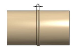
Measured outside of the pipe after completion of the cooling time.
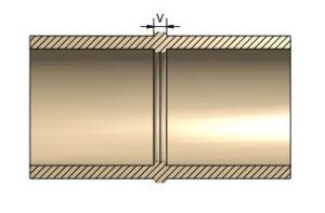
The form is read as the minimum wall thickness. For example, if the wall thickness measured on the pipe is 10 mm, go up in the table to the nearest = 9 mm and read the bead width next to it. = permissible bead width 8-11mm
When using moldings (and pipes against the molding), the tolerance is extended by +/- 1 mm. (in the above example permissible bead width 7-12mm).
Table 1 Single Pressure Butt Fusion Jointing Conditions for PE80 and PE100
Outside diameter (mm) | SDR | Typical final overall bead width (min.) | Typical final overall bead width (max.) |
|---|---|---|---|
| 90 | 17 | 8 | 15 |
| 90 | 11 | 9 | 16 |
| 110 | 17 | 9 | 16 |
| 110 | 11 | 10 | 17 |
| 125 | 17 | 9 | 16 |
| 125 | 11 | 10 | 17 |
| 160 | 17 | 9 | 16 |
| 160 | 11 | 11 | 18 |
| 180 | 17 | 10 | 17 |
| 180 | 11 | 11 | 18 |
| 225 | 17 | 10 | 17 |
| 225 | 11 | 12 | 19 |
| 250 | 26 | 9 | 16 |
| 250 | 17 | 10 | 17 |
| 280 | 26 | 13 | 22 |
| 280 | 17 | 14 | 23 |
| 315 | 26 | 13 | 22 |
| 315 | 17 | 14 | 23 |
Table 2 Dual Pressure Butt Fusion Jointing Conditions for PE80 and PE100
Outside diameter (mm) | SDR | Typical final overall bead width (min.) | Typical final overall bead width (max.) |
|---|---|---|---|
| 250 | 11 | 15 | 24 |
| 280 | 11 | 16 | 25 |
| 315 | 11 | 17 | 26 |
| 355 | 11 | 18 | 27 |
| 400 | 17 | 15 | 24 |
| 400 | 11 | 18 | 27 |
| 450 | 17 | 16 | 25 |
| 450 | 11 | 19 | 28 |
| 500 | 17 | 17 | 26 |
| 500 | 11 | 20 | 29 |
| 560 | 17 | 17 | 26 |
| 560 | 11 | 22 | 31 |
| 630 | 26 | 16 | 25 |
| 630 | 17 | 18 | 27 |
| 630 | 11 | 23 | 32 |
| 710 | 26 | 16 | 25 |
| 710 | 17 | 19 | 28 |
| 800 | 26 | 17 | 26 |
| 800 | 17 | 20 | 29 |
| 900 | 26 | 18 | 27 |
| 900 | 17 | 22 | 31 |
| 1000 | 26 | 19 | 28 |
| 1000 | 17 | 23 | 32 |
| 1200 | 26 | 31 | 30 |
| 1200 | 17 | 26 | 35 |
